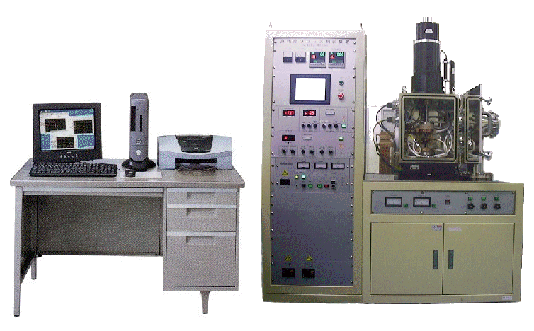
■
TEST ITEM
|
1. formastor-F function
|
| |
Measurement of Ac1 , Ac3 transformation temperature.
|
| |
Measurement of continuous cooling transformation and [CCT diagram] making.
|
| |
Measurement of Time Temperature Transformation and [TTT
diagram] making.
|
| |
Measurement of martensite transformation (Mf).
|
| |
[Specimen]
φ8×L12 : round bar, φ6×L120
: round bar, t0.5~3.2× W10×L80
: sheet |
|
|
2. Thermecmastor-Z function
|
| |
Hot Compression Test
(φ8×L12 : round bar)
|
| |
Hot Tensile Test (φ6×L120
: round bar, t0.5~3.2×W10×L80
: sheet
) |
|
|
■Configuration
within the scope estimate.
1. Testing Machine
(Main Body )
|
Included ・・・Heating / Cooling / Deformation system |
|
2. Vacuum Chamber / Exhaust Unit
|
Included ・・・Atmosphere Making system |
|
|
3. High Frequency Generator |
|
4. Turning-on-electricity heating device |
|
5. Control Panel
(Console ) |
|
6. Computer System
(Hardware & Software ) |
|
7. Accessories |
| 8. Optional Unit and Device
|
|
9. Installing Workss |
|
■Specifications Note
: * It is decided by a specimen.
|
1. Heating
・・・by High Frequency Induction Heating and Turning-on-electricity heating device |
| |
1) Temperature Range |
R.T ~1600 deg.C
(sensor [R]TC )
|
| |
2) Heating Rate
* |
20~100 deg..C
/sec |
| |
3) Temp Distribution |
+/- 10 deg..C (on Uniformity area) |
| |
4) Control Accuracy |
+/- 1 deg..C (only Controller) |
|
|
2. Cooling
・・・ by Cooling Gas or Water Spray from Nozzles |
| |
1) Temperature Range |
1400
deg.C~R.T. (sensor [R]TC ) |
| |
2) Cooling Rate* |
(1) Gas : Max. 60 deg.C / sec (He gas 0.7MPa
)
|
| |
|
(2) Water : Max. 300 deg.C /sec
(0.5MPa) |
| |
3 ) Time Distribution |
+/-
20% (to the set cooling time
)
|
|
|
3. Load |
| |
1) Load Output |
Static Max.20KN |
| |
2)
Piston Stroke |
100mm |
| |
3 ) Load Rate |
0.05~50mm/sec |
| |
4 ) Working Quantity |
(1) Tensile
: 50mm |
| |
|
(2) Compression
: 10mm |
| |
5 ) Control System |
(1) Displacement Control |
| |
|
(2) Load Control |
| |
6 ) Control Pattern |
(1) "Load/Stroke
vs Time"
Pattern |
| |
|
(2) "Strain
vs Time"
Pattern |
| |
|
(3) "Strain Velocity Constant"
Pattern |
| |
7) Control Accuracy |
+/- 1% (Against Controlling Load/Stroke FS
)
|
|
|
4.
Atmosphere
Making
・・・By
Exhaust
Unit &
Atmosphere
Making
Circuit |
| |
1)
Configuration / Vacuuming Rate |
Rotary
Pump
:
6.6×100Pa
/
15min |
| |
|
Diffusion Pump
: 1.3×10⁻²Pa
/
15min |
| |
2)
Attainable Vacuum |
1.3×10⁻²Pa
order |
| |
3
)
Atmospheric Gas |
Inart
Gas |
|
|
5.
Computer
System(Hardware
& Software) |
| |
1)
Configuration |
Computer
Unit,
LCD-Display
,Inkjet-Printer |
| |
2)
CPU |
Pentium
Ⅳ, 32bit, 512MB |
| |
3
)
Media |
HD
: 80MB, FD
: 1.4MB, CD
: CD-RW |
| |
4
)
Operating System |
Windows-XP |
| |
5
)
Application system |
FDCPRG |
|
|
6.
FDCPRG
DATA
ANALYSIS |
| |
1)
TimeDP Program |
Time-Temp, Load, Stroke
Curve |
| |
2)
SSDP Program |
Stress-Strain Curve
・・・Uni-axial
Compression |
| |
3
)
STDP Program |
Stress-Strain
Curve
・・・Tensile |
| |
4
)
XXDP Program
|
Over-write
Curve
for
SSDP, STDP |
|
|
7.
Accessories |
| |
1)
Thermocouple
Welder |
for Temperature
detecting |
| |
2)
Jig
& Chuck |
Upper & Lower
Jig, Anvil |
| |
3
)
Heating
Coil |
Uni-axicial
Compression, Tensile |
| |
4
)
Anvil |
φ20×L40
ceramic, quartz |
| |
|
φ10×t0.2
mica sheet |
| |
5
)
Temp
Detect
Parts |
TC, Insulation
Tube, Nylon
Tube |
| |
6
)
Recording
Parts |
Cartridge
Pen, Ink, Chart
Paper, Printing
Paper |
| |
7)
Software |
Windows XP, FDCPRG |
| |
8)
Vacuum
Parts, HFG
Parts, Panel
Parts, etc |
|
|
8.
OPTIONAL
UUNIT |
| |
1))Cooling
Method |
Fin &
Tube forced
Air Cooling |
| |
2)
Cooling
Capacity |
20lkW
at
20 deg.C |
| |
3
)
Circulation
Water |
60
lit/min
at
0.5MPa |
| |
4
)
AC
Power |
φ3
220V
11.4kW (39A) |
|
|
|
|

